For my fellow enginerds:
1. Transverse bottom-flange PT: 4x0.6" dia, 7-wire strands, GROUTED tendons @ 2'6" spacing. These tendons were fully stressed, capped and grouted BEFORE transportation.

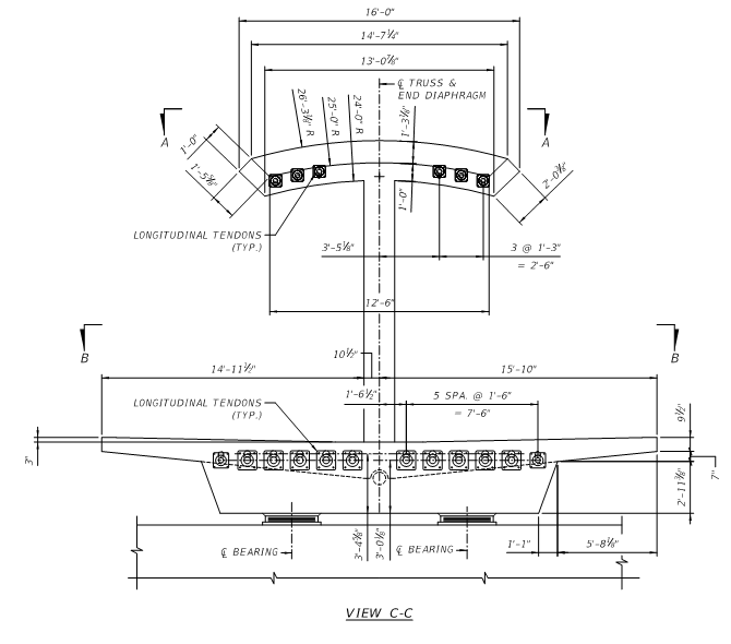
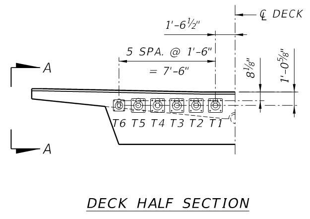
2. Longitudinal bottom-flange PT: 10 groups of 19x0.6" dia, 7-wire strands, GROUTED tendons typically, except T6 were 12 strand tendons. These tendons were fully stressed, capped and grouted BEFORE transportation.
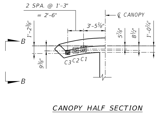
3. Longitudinal top-flange (canopy) PT: 4 groups of 12x0.6" dia, 7-wire strands, GROUTED tendons typically, except C3 were 7 strand tendons, GROUTED. These tendons were fully stressed, capped and grouted BEFORE transportation.
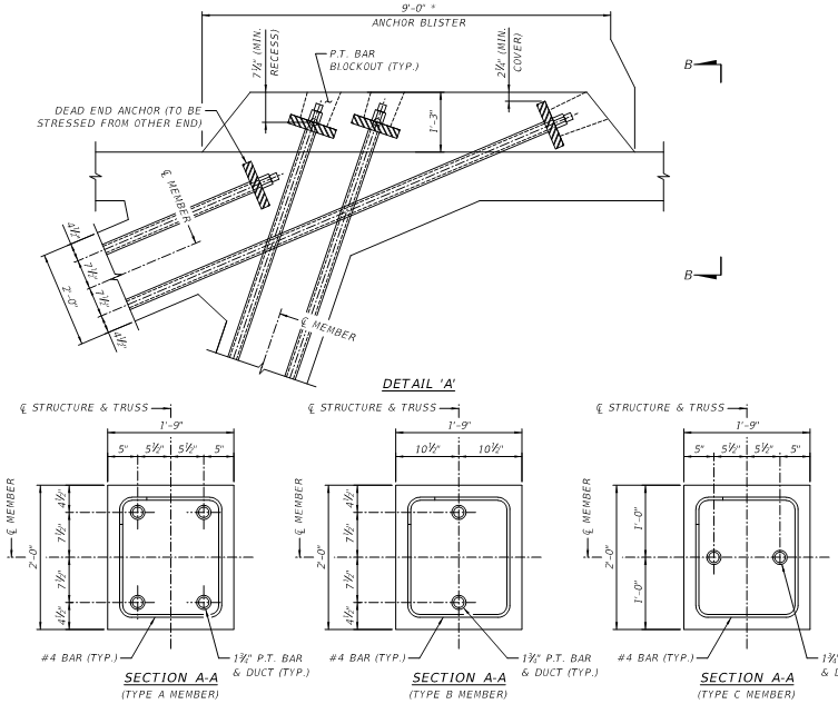
4. Truss diagonal member axial PT: 1-3/4" PT bar (probably Grade 150 ksi), probably full-threaded. I would expect that the majority of these PT bars would have been stressed, capped and grouted BEFORE transportation EXCEPT for the temporary PT in the end diagonals.